Ask Latest Price
Verified Supplier
9 Years

Ningbo Sanmin Import And Export Co.,Ltd.
Ningbo Sanmin Import And Export Co.,Ltd.


Add to Cart
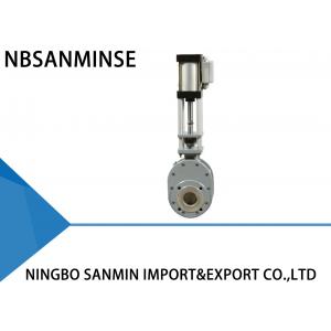
SMWZ644 ( 1 ) -10 ( 2 )- DNB -( 3 ) Penumatic Wear -proof Double Discs Valve ( Inlet Valve /Outlet Valve / Balance Valve ) Double gate valve
Main Perfomance
Model WZ644-10Q double-disc valve uses a double -disc sealing and sealing surfaces are made from wear-resistant alloy or ceramic. The seal is 100% airtight and the valve achieves a long service life , particularly in applications . Consequently , overall system reliability is increased dramatically .
Operating Performance
When air is introduced into the upper cylinder port , the piston rod pushes the double-disc down and the valve is closed . When air is introduced into the lower cylinder port , the piston rod pushes the double-disc up and the valve is opened . Compression spring being placed between the discs and seal ring , forces the discs the discs against the seal ring , and also allow for discs vertical movement , which helps to compensate the thermal expansion and contraction of the parts and ensure an airtight seal under all conditions . When actuating the valve , the double-disc rotates to lap and polish the sealing surfaces . When product flows through the valve , any material entering the inner chamber is removed by vortex flow action . Hence , the valve is self-cleaning . Additional air purging can be provided to ensure clean-in-place performance . All these characteristics guarantee a long service lofe for the valve and increase the reliability of your system .
Applications
Any dust , powder , and granular products in coal-fired power plants , smelters , iron and steel plants , pharmaceutical and chemical industries .
Technical Parameters
Maximum-Operating Pressure : 1.0MPa
Maximum Test Pressure : 1.5MPa
Operating Temperature : <200℃
Leakage Test Pressure : 1.1MPa
Installation and Application
1. Prior to installation , make sure the pneumatic actuator is free of any defects like breakage and concave .
2. Make sure the joint flange , structural length , maximum operating pressure and nominal diameter are accorded with requirements .
3. During installation , not allowed to readjust studs and nuts that have been fastened originally . Align the center of two pipelines and valve diameter to be coaxial . Keep the flange surface flat . Uniformly apply force to tighten the bolt .
4. After installation , introduce air from the upper and lower cylinder ports to see whether the valve can be normally opened or closed .
5. Cheek the control switch ( if existing ) to see whether it is reliably fastened , whether its parameter is accorded with access power source , and whether it can correctly work under full opening and full closing conditions .
Troubleshooting Method
| Troubles | Cause | Troubleshooting Method |
| Leakage in sealing surface | Dirt between disc and sealing surface | Remove the dirt |
| Damage to seal ring pairs | Repair or replace | |
| Leakage in flange joint | The bolt is unevenly screwed | Evenly screw the bolt |
| Damage to the flange surface | Repair the flange surface | |
| Damage to the spacer | Replace the spacer | |
| Valve fails to be correctly opened or closed | Dust deposit | Remove dust regularly |
| Insufficient air pressure , severe leakage | Repair air supply pipeline | |
| Pneumatic components have been aged and lost efficlency | Replace the damaged components | |
| Leakage of stuffing box | The stuffing has been aged and severely worn | Replace the stuffing |
Main Parts and Materials
| Item | Name | Material | Item | Name | Material |
| 1 | Valve body | Ductile iron | 5 | Connecting T-piece | Cast steel |
| 2 | Side valve body | Ductile iron | 6 | End cap | 45#Steel |
| 3 | Sealing ring | Carbon steel + special alloy | 7 | Linking neck | Hodular cast iron |
| 4 | Dise | Carbon steel + special alloy | 8 | Pneumatic actuator aluminum | Aluminum cylinder |
